Scan to BIM Explained: Benefits, Process and Real-World Use Cases
Scan to BIM Explained: Benefits, Process and Real-World Use Cases
If you have ever walked into a building renovation project and found that the original drawings do not match what is actually there, you already understand the problem that Scan to BIM solves.
Outdated floor plans, missing structural details, undocumented MEP systems these gaps cost real money. Rework, design clashes, and budget blowouts are the predictable result. Scan to BIM closes that gap by turning a physical building into an accurate, data-rich 3D model that the entire project team can work from.
Here is a clear explanation of what Scan to BIM is, how the process works, and where it gets used in the real world.
What Is Scan to BIM?
Scan to BIM is the process of capturing the exact physical conditions of an existing building or structure using a 3D laser scanner, then converting that scan data into an intelligent Building Information Model (BIM).
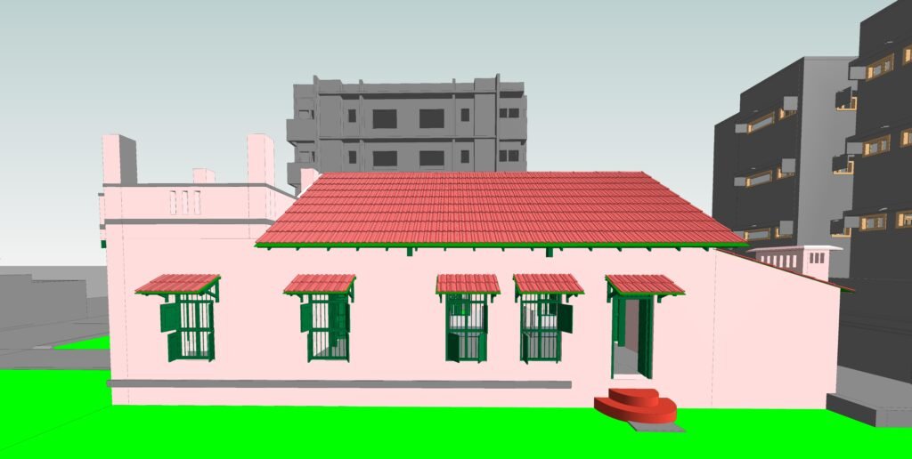
Here is what that means in practice. A laser scanner fires millions of pulses of light across a space and records precisely where each pulse reflects back. The result is a dense, three-dimensional map of every surface, wall, column, ceiling, duct, and pipe in the building. This map is called a point cloud.
That point cloud becomes the raw material for a BIM model. Trained modellers work inside platforms like Autodesk Revit, tracing over the point cloud to build intelligent 3D objects walls that know they are walls, pipes that carry material and diameter data, columns with structural properties. The finished model reflects what the building actually looks like, not what someone drew 20 years ago.
The global BIM in construction market was valued at USD 5.06 billion in 2024 and is projected to reach USD 17.95 billion by 2033, growing at a CAGR of 15.1% from 2025 to 2033, which tells you the industry is moving firmly in this direction.
How the Scan to BIM Process Works: Step by Step
Let’s break it down from first scan to final deliverable.
Step 1: Define the Scope
Before a scanner enters the building, the project team agrees on a Scope of Work (SOW). This covers which building elements need to be modelled, the required Level of Detail (LOD), acceptable tolerance levels, and file format requirements. Getting this right upfront prevents expensive revisions later.
Step 2: Laser Scanning on Site
A surveyor or scanning specialist sets up the laser scanner at multiple positions throughout the building. At each station, the scanner captures a full 360-degree point cloud. Multiple scans are taken from overlapping positions so that the entire space is covered with no gaps.
Common scanners used in professional workflows include the Leica RTC360, FARO Focus Premium, and NavVis VLX for mobile scanning. Each captures millions of data points per second.
Step 3: Point Cloud Registration and Processing
Back in the office, raw scan data is imported into processing software such as Autodesk ReCap Pro or CloudCompare. Individual scans from each station are aligned and stitched together using common reference points. The merged point cloud is then cleaned to remove noise, and the file is geo-referenced so every point has a real-world coordinate.
The output at this stage is typically an .RCP or .E57 file, which loads directly into Revit for modelling.
Step 4: BIM Modelling in Revit
This is where the point cloud becomes an intelligent model. BIM modellers import the registered point cloud into Autodesk Revit and begin tracing building elements over it. Walls, floors, columns, beams, ceilings, doors, windows, and MEP components are built as parametric Revit objects.
Real buildings are never perfectly flat or plumb. A skilled modeller decides, based on the project brief, whether to model what is actually there (true as-built geometry, common for heritage projects) or model to a corrected design intent (useful for renovation planning). This distinction matters and should be agreed on before modelling begins.
Step 5: Quality Check and Delivery
The finished model is checked against the original point cloud to confirm that all elements are captured accurately and that LOD requirements are met. Deliverables are then handed over in agreed formats, commonly .RVT for Revit, with supporting PDFs of floor plans, sections, and elevations.
Understanding LOD in Scan to BIM
LOD, or Level of Development, tells everyone on the project how much detail and information a BIM model contains. Choosing the right LOD saves time and keeps costs proportional to what the project actually needs.
Here is a practical guide:
| LOD Level | What It Contains | When to Use It |
| LOD 100 | Basic massing, approximate dimensions | Early feasibility and space planning |
| LOD 200 | Approximate geometry, spatial relationships | Schematic design, coordination |
| LOD 300 | Accurate geometry, specific assemblies | Construction documentation, clash detection |
| LOD 350 | Detailed geometry plus connection information | MEP coordination, prefabrication planning |
| LOD 400 | Fabrication-level detail | Manufacturing, specialist trade coordination |
For most renovation projects, LOD 300 paired with a measurement tolerance of ±5mm covers the majority of needs. Heritage documentation and MEP-heavy industrial sites often require LOD 400.
A common as-built deliverable pairs LOD 300 with LOA (Level of Accuracy) 30, meaning the model geometry is specific and the measurement tolerance is ±5mm against the scan. These two specifications are separate LOD describes the representation, LOA describes how closely the model matches the physical scan.
Key Benefits of Scan to BIM
Here is why architects, engineers, and project managers choose this workflow over traditional surveying.
Accuracy That Manual Surveys Cannot Match
Traditional tape measures and total station surveys rely on spot measurements taken at specific points. Scan to BIM captures the entire space at once, producing models with tolerances of ±3–5mm across architectural, structural, and MEP disciplines. That kind of accuracy means design teams can work with confidence, knowing the model reflects the actual building.
Faster Data Collection
A single operator with a laser scanner can cover a floor of a commercial building in hours. Traditional surveys of the same space could take days. For large sites industrial plants, hospitals, multi-storey commercial buildings the time difference is dramatic.
Fewer Clashes and Less Rework
One case study from a hospital renovation project in California found that adopting laser scan-to-BIM services produced 40% faster modelling time and 25% cost savings by eliminating rework that stemmed from inaccurate as-built drawings. When design teams have an accurate model to work from, they catch clashes in software instead of discovering them on site where fixes cost far more.
For context, a McKinsey report from 2023 noted that 75% of construction projects exceed their budgets and 70% experience schedule overruns, often tied to outdated drawings or design clashes.
Safe Documentation of Inaccessible Areas
Laser scanners can capture plant rooms, roof voids, and hazardous industrial environments remotely. Surveyors do not need to spend extended time in confined or dangerous spaces. The scanner does the work.
A Permanent Digital Record
The point cloud and resulting BIM model become a permanent reference asset for the building. Facility managers, future renovation teams, and maintenance contractors can return to the same model years later, avoiding the cost of re-surveying.
Better Collaboration Across Teams
A centralized BIM model built from scan data gives architects, structural engineers, MEP consultants, and contractors a single source of shared information. Everyone works from the same geometry, reducing miscommunication at every stage of the project.
Real-World Use Cases for Scan to BIM
Scan to BIM gets used across a broader range of project types than many people expect. Here are the main areas where it delivers clear returns.
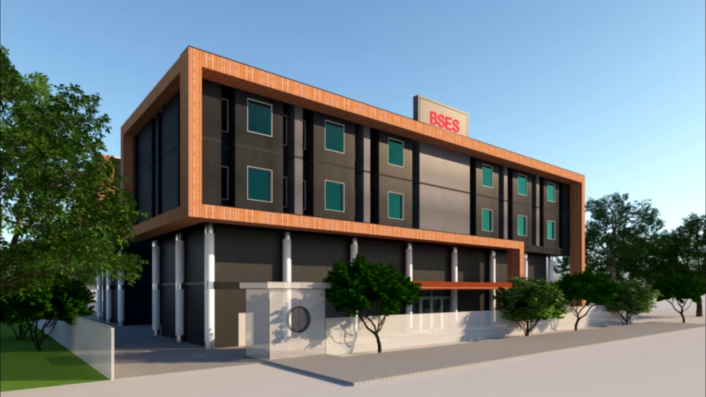
Renovation and Retrofit Projects
This is the most common application. When a team is renovating an existing building, they need accurate as-built documentation before any design work begins. Scan to BIM replaces guesswork with measured reality, giving designers the foundation they need to plan fit-outs, structural changes, or façade upgrades accurately.
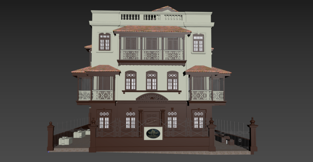
Heritage and Conservation Projects
Historic buildings rarely have accurate original drawings. Shayona Tech, a global BIM specialist based in Ahmedabad, applies Scan to BIM specifically to heritage conservation work, capturing the precise geometry of historical structures for restoration, conservation planning, and structural analysis.
For listed buildings and monuments, where every decision carries weight, having a millimetre-accurate model of the existing structure is not a luxury it is a requirement.
MEP Coordination and Clash Detection
Mechanical, electrical, and plumbing systems in complex buildings occupy the same ceiling voids, shaft spaces, and plant rooms. Clash detection in Revit using point cloud data can prevent field change orders worth USD 15,000 or more per conflict found. For large commercial or industrial projects, that adds up quickly.
Facilities Management and Digital Twins
Building owners use Scan to BIM to create a digital foundation for ongoing facilities management. The model connects to IoT data for real-time monitoring, helping managers track energy usage, plan maintenance schedules, and model space changes before any physical work begins. This combination of scan data and live building performance feeds what is known as a digital twin.
Industrial and Plant Modelling
Oil and gas facilities, manufacturing plants, and process industries depend on precise documentation of piping systems, structural steelwork, and equipment layouts. Scan to BIM captures the actual position of every pipe run and structural member, producing plant models that support maintenance, expansion planning, and safety assessments.
Infrastructure and Corridor Projects
Bridges, tunnels, and transport corridors benefit from scan-based BIM models for condition assessments, maintenance planning, and expansion design. Mobile LiDAR and airborne scanning collect data across long stretches of infrastructure quickly, feeding BIM models for engineering analysis.
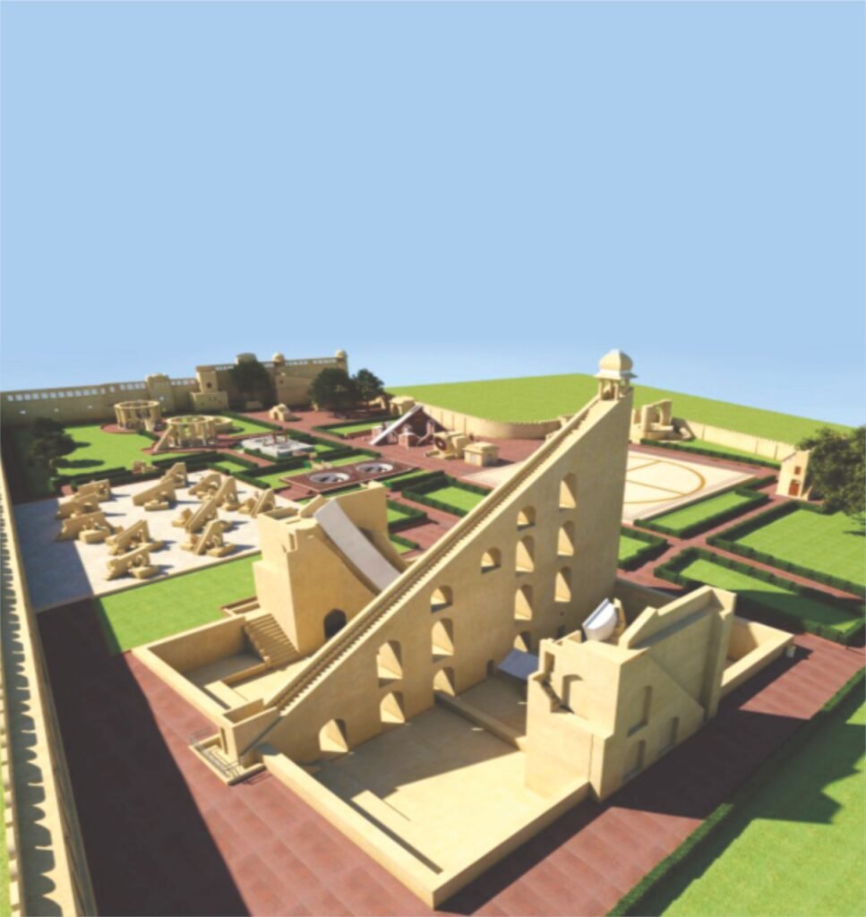
Smart City Modelling
City governments and urban planners use Scan to BIM at a city scale to build 3D models of built environments for planning, infrastructure management, and disaster response. Shayona Tech’s smart city modelling service builds on this same workflow, integrating buildings, infrastructure, and terrain into a unified digital model.
Software Used in Scan to BIM Workflows
Here are the tools most commonly used across the workflow:
- Point cloud processing: Autodesk ReCap Pro, CloudCompare, FARO Scene
- BIM modelling: Autodesk Revit (most common), ArchiCAD, Bentley MicroStation, Tekla Structures
- Coordination and clash detection: Autodesk Navisworks
- File formats: .RCP and .RCS (Revit-compatible point cloud formats), .E57 (open standard for 3D data exchange), .RVT (Revit project file)
Revit 2025 and later versions support direct E57 import without needing to convert through ReCap Pro first, which simplifies the workflow for teams working with newer scan data.
What Makes a Scan to BIM Project Successful?
A few decisions made early in the project determine the quality of the final model.
Clear LOD specification. Agreeing on the required Level of Development before scanning begins prevents mismatches between what the team expects and what is delivered.
Good scan coverage. Gaps in the point cloud create gaps in the model. Experienced scanning teams plan scan positions to ensure every part of the building is covered with sufficient overlap between stations.
Skilled modellers. Converting a point cloud to a BIM model requires both BIM software knowledge and construction understanding. A modeller needs to recognise what they are looking at in the scan a structural column versus a cladding element, a supply duct versus a return duct to build the right objects with the right properties.
Defined tolerances. A typical as-built model achieves ±3–5mm tolerance for LOD 300 work. Tighter tolerances are possible but require more modelling time and come at higher cost. Setting realistic expectations on tolerances before work begins keeps the project on track.
Scan to BIM at Shayona Tech
Shayona Tech, founded in 2012 and based in Ahmedabad, India, works with clients in architecture, engineering, construction, infrastructure, and heritage conservation. The team converts point cloud data from 3D LiDAR scans into accurate, intelligent BIM models using Revit, working to LOD standards from 100 through to 500 depending on project requirements.
Their Scan to BIM service covers residential buildings, commercial complexes, infrastructure assets, industrial facilities, and heritage monuments. The team also provides supporting services including 3D LiDAR scanning, drone UAV surveys, as-built modelling, LiDAR data processing, and plant modelling which means the entire workflow from physical scan to finished BIM model can be handled by a single team.
For projects where both the scanning and the modelling need to meet global standards, working with a specialist like Shayona Tech removes the coordination risk of managing separate scanning and BIM teams.
Common Challenges and How to Address Them
High initial cost. The scanning hardware, software, and skilled personnel carry real upfront cost. That cost is usually recoverable through reduced rework and faster design. For small projects, a clear cost-benefit assessment before committing is sensible.
Large file sizes. Point cloud files are dense. Processing and storing them requires solid IT infrastructure. Well-managed workflows decimate the point cloud (reduce file size without losing useful geometry) before loading it into Revit.
Reflective and transparent surfaces. Glass, polished metal, and water absorb or scatter laser pulses, creating gaps or noise in the scan. Experienced operators adjust scanner settings and supplement with additional scan positions to cover these areas.
Skilled workforce. The combination of scanning skills and BIM modelling skills in one team is not universal. Firms without in-house capability often work with specialist Scan to BIM service providers.
FAQs About Scan to BIM
Q1: How is Scan to BIM different from traditional as-built surveying?
Traditional as-built surveys rely on manual measurements taken at individual points. Scan to BIM captures the entire space with millions of data points in a single session, producing far more complete and accurate documentation. The result is a 3D model rather than a set of 2D drawings, and it contains far more information for the project team to work from.
Q2: What Level of Detail (LOD) do I need for my renovation project?
For most renovation and fit-out projects, LOD 300 is sufficient. It gives you accurate geometry, correct dimensions, and element-level information for design and construction documentation. LOD 350 or 400 is worth specifying for complex MEP coordination, prefabrication, or heritage restoration where every detail matters.
Q3: How long does a Scan to BIM project typically take?
Scanning a typical commercial floor takes one to two days on site. Modelling that scan data into a Revit model at LOD 300 for a 50,000 square foot building usually takes one to three weeks, depending on complexity and MEP density. Heritage or industrial projects with more detail requirements take longer.
Q4: Can Scan to BIM be used on buildings without any existing drawings?
Yes, and this is one of its strongest use cases. For older buildings where original drawings are missing, incomplete, or unreliable, Scan to BIM produces accurate documentation from scratch. The scan captures what is actually there, independent of any prior paperwork.
Q5: What deliverables should I expect from a Scan to BIM project?
Standard deliverables include a Revit (.RVT) model at the agreed LOD, floor plans, sections, interior and exterior elevations, and in many cases the registered point cloud file (.RCP or .E57) for reference. Some providers also deliver lightweight viewer files so non-Revit users on the team can review the 3D model in a web browser.